Product Description
SWL series skillful manufacture screw reducer:
1.Convenient to adjust
2.Wide range of ratio
3.Easy to install
4.high torque
Application Industries:
Our SWL series screw jacks are widely used in the industries such as metallurgy,mining,hoisting and transportation, electrical power,energy source,constrction and building material,light industry and traffice industry
Product Parameters
|
Type |
Model |
Screw thread size |
Max |
Max |
Weight without stroke |
Screw weight |
|
SWL Screw jack |
SWL2.5 |
Tr30*6 |
25 |
25 |
7.3 |
0.45 |
|
SWL5 |
Tr40*7 |
50 |
50 |
16.2 |
0.82 |
|
|
SWL10/15 |
Tr58*12 |
100/150 |
99 |
25 |
1.67 |
|
|
SWL20 |
Tr65*12 |
200 |
166 |
36 |
2.15 |
|
|
SWL25 |
Tr90*16 |
250 |
250 |
70.5 |
4.15 |
|
|
SWL35 |
Tr100*18 |
350 |
350 |
87 |
5.20 |
|
|
SWL50 |
Tr120*20 |
500 |
500 |
420 |
7.45 |
|
|
SWL100 |
Tr160*23 |
1000 |
1000 |
1571 |
13.6 |
|
|
SWL120 |
Tr180*25 |
1200 |
1200 |
1350 |
17.3 |
|
1.Compact structure,Small size.Easy mounting,varied types. Can be applied in 1 unit or multiple units. |
||||
|
2.High reliability.Long service life; With the function of ascending,descending,thrusting,overturning |
||||
|
3.Wide motivity.It can be drived by electrical motor and manual force. |
||||
|
4.It is usually used in low speed situation,widely used in the fields of |
Detailed Photos
PRODUCT SPECIFICATIONS
SWL Series
Swl series worm screw lift is a kind of basic lifting component, which can lift, lower, propel, turn and other functions through the worm drive screw.
Screw jack can be widely used in machinery, metallurgy, construction, chemical, medical, cultural and health, and other industries. Can according to a certain procedure to accurately control the adjustment of the height of ascension or propulsion, can be directly driven by motor or other power, can also be manually. This series of worm screw lift can be self-locking, with the bearing capacity ranging from 2.5 tons to 120 tons, the maximum input speed of 1500 r/min, and the max lifting speed of 2.7 m/min.
Features:
1. Suitable for heavy load, low speed and low frequency;
2. Main components: precision trapezoid screw pair and high precision worm gear pair.
3. Compact design, small volume, light weight, wide drive sources, low noise, easy operation, convenient
maintenance.
4. The trapezoid screw has self-locking function, it can hold up load without braking device when screw stops traveling.
5. The lifting height can be adjusted according to customer requirements.
6. Widely applied in industries such as machinery, metellurgy, construction and hydraulic equipment.
7. Top End: top plate, clevis end, threaded end, plain end, forked head and rod end.
|
1. screw rod |
2. nut bolt |
3. cover |
4.Skeleton oil seal |
5.Bearing |
|
6.Worm gear |
7.Oil filling hole |
8.Case |
9.Skeleton oil seal |
10.Cover |
|
11. nut bolt |
12.Bearing |
13.Skeleton oil seal |
14.Bearing |
15.worm |
|
16.Flat key |
17.Bearing |
18.Skeleton oil seal |
19.Cover |
20.Nut bolt |
Product Description
|
MODEL |
|
SWL2.5 |
SWL5 |
SWL10 |
SWL15 |
SWL20 |
SWL25 |
SWL35 |
|
Maximum lifting force (kN) |
|
25 |
50 |
100 |
150 |
200 |
250 |
350 |
|
Screw thread size |
|
Tr30*6 |
Tr40*7 |
Tr58*12 |
Tr58*12 |
Tr65*12 |
Tr90*16 |
Tr100*20 |
|
Maximum tension (kN) |
|
25 |
50 |
99 |
166 |
250 |
350 |
|
|
Worm gear ratio (mm) |
P |
1/6 |
1/8 |
3/23 |
1/8 |
3/32 |
3/32 |
|
|
|
M |
1/24 |
1/24 |
1/24 |
1/24 |
1/32 |
1/32 |
|
|
Worm non rotating stroke (mm) |
P |
1.0 |
0.875 |
1.565 |
1.56 |
1.5 |
1.875 |
|
|
M |
0.250 |
0.292 |
0.5 |
0.5 |
0.5 |
0.625 |
||
|
Maximum elongation of screw rod under tensile load (mm) |
|
1500 |
2000 |
2500 |
3000 |
3500 |
4000 |
|
|
Maximum lifting height at maximum pressure load (mm) |
The head of the screw rod is not guided |
250 |
385 |
500 |
400 |
490 |
850 |
820 |
|
Lead screw head guide |
400 |
770 |
1000 |
800 |
980 |
1700 |
1640 |
|
|
Worm torque at full load(N.m) |
P |
18 |
39.5 |
119 |
179 |
240 |
366 |
464 |
|
M |
8.86 |
19.8 |
60 |
90 |
122 |
217 |
253 |
|
|
efficiency(%) |
P |
22 |
23 |
20.5 |
|
19.5 |
16 |
18 |
|
M |
11 |
11.5 |
13 |
|
12.8 |
9 |
11 |
|
|
Weight without stroke(kg) |
|
7.3 |
16.2 |
25 |
|
36 |
70.5 |
87 |
|
Weight of screw rod per 100mm(kg) |
|
0.45 |
0.82 |
1.67 |
|
2.15 |
4.15 |
5.20 |
SWL Worm Gear Screw Jack Mounting Dimensions
| Standard or Nonstandard: | Nonstandard |
|---|---|
| Application: | Textile Machinery, Garment Machinery, Conveyer Equipment, Electric Cars, Motorcycle, Food Machinery, Marine, Mining Equipment, Agricultural Machinery, Car, Power Transmission |
| Input Speed: | 8-360rpm |
| Gear Material: | Low Carbon High Alloy Steel |
| Gearing Arrangement: | Worm |
| Mounting Position: | Horizontal (Foot Mounted) or Vertical (Flange Moun |
| Samples: |
US$ 50/Piece
1 Piece(Min.Order) | |
|---|
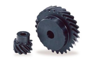
What are the advantages and disadvantages of using screw gears?
Using screw gears, also known as worm gears, offers several advantages and disadvantages. These gears have unique characteristics that make them suitable for specific applications but may also present limitations in certain scenarios. Here’s a detailed explanation of the advantages and disadvantages of using screw gears:
Advantages:
- High Gear Ratio: Screw gears provide high gear ratios, meaning that a small rotation of the worm gear can result in a significant rotation of the worm wheel. This high gear ratio allows for precise control and slow movement, making screw gears suitable for applications that require fine adjustments and positioning accuracy.
- Self-Locking: Screw gears have a self-locking characteristic, which means that they can hold their position without the need for additional braking mechanisms or external locking devices. This feature is particularly useful in applications where load holding or preventing back-driving is essential, such as in lifting systems or incline conveyors.
- Compact Design: Screw gears have a compact design due to their single-threaded helical shape. This compactness allows for space-saving installations, making screw gears advantageous in applications with limited space or tight packaging requirements.
- Quiet Operation: Screw gears typically operate with reduced noise levels compared to other gear types. The sliding contact between the worm gear and the worm wheel results in less gear mesh noise, making screw gears suitable for applications that require low noise levels or quiet operation.
Disadvantages:
- Lower Mechanical Efficiency: Screw gears generally have lower mechanical efficiency compared to other gear types, such as spur gears or helical gears. The sliding motion between the worm gear and the worm wheel generates more friction, leading to energy losses and reduced efficiency. However, advancements in gear design, materials, and lubrication can help mitigate this disadvantage to some extent.
- Limited Power Transmission Capacity: Screw gears are typically not suitable for high-power transmission applications. Due to the sliding contact and high gear ratios, they may have limitations in terms of torque capacity. In high-power applications, other gear types, such as spur or helical gears, are often preferred due to their higher load-carrying capabilities.
- Potential Backlash: Screw gears can exhibit backlash, which refers to the play or clearance between the mating teeth of the worm gear and the worm wheel. Backlash can lead to reduced accuracy, vibration, and inefficient power transmission. Minimizing backlash through precise manufacturing and proper gear meshing is crucial to mitigate this issue.
- Requires Proper Lubrication: Screw gears rely on adequate lubrication to minimize friction and ensure smooth operation. Proper lubrication is essential to prevent excessive wear, overheating, and premature failure. Regular maintenance and lubrication checks are necessary to maintain the efficiency and lifespan of screw gear systems.
- Manufacturing Complexity: The manufacturing process of screw gears can be more complex compared to other gear types. Achieving precise gear tooth profiles and maintaining proper gear meshing requires careful machining and specialized equipment. This complexity can increase manufacturing costs and lead times.
When considering the use of screw gears, it is important to evaluate the specific requirements of the application, such as the need for high gear ratios, load capacity, positional accuracy, and noise levels. By carefully assessing the advantages and disadvantages, engineers can determine whether screw gears are the most suitable choice for their particular application.
How do you retrofit an existing mechanical system with screw gears?
Retrofitting an existing mechanical system with screw gears, also known as worm gears, involves replacing or modifying the existing gear system to incorporate screw gears. Here’s a detailed explanation of the steps involved in retrofitting an existing mechanical system with screw gears:
- Evaluate the Existing System: Begin by evaluating the existing mechanical system to understand its design, function, and the specific requirements for retrofitting. Identify the type of gears currently in use and assess their limitations or shortcomings that warrant the retrofit. Consider factors such as load capacity, speed requirements, space constraints, and the desired performance improvements.
- Analyze Compatibility: Determine the compatibility of screw gears with the existing system. Consider factors such as available space, alignment requirements, torque and speed requirements, and the feasibility of integrating screw gears into the system. Assess whether any modifications or adaptations are needed to accommodate the screw gears effectively.
- Design Considerations: Based on the evaluation and compatibility analysis, develop a design plan for incorporating screw gears into the existing system. Consider aspects such as gear ratios, torque requirements, lubrication systems, mounting arrangements, and any necessary modifications to the system components or structure. Ensure that the design meets the specific performance and functional objectives of the retrofit.
- Select Screw Gear Components: Choose the appropriate screw gear components based on the design requirements and the specifications of the existing system. Consider factors such as gear material, tooth profile, helix angle, pitch diameter, and the number of starts. Select components that are compatible with the load, speed, and operating conditions of the retrofit application.
- Fabrication or Procurement: Once the screw gear components are selected, proceed with the fabrication or procurement of the required parts. This may involve manufacturing the screw gear components or purchasing them from a reliable supplier. Ensure that the components meet the specified quality standards and are suitable for the retrofit application.
- Installation: Install the screw gears into the existing mechanical system as per the design plan. This may involve removing the old gears and replacing them with the new screw gears or modifying the existing gear system to accommodate the screw gears. Follow proper installation procedures, ensuring correct alignment, lubrication, and torque specifications.
- Testing and Adjustment: After the installation, conduct thorough testing of the retrofitted system to verify its performance and functionality. Check for proper gear engagement, smooth operation, and the ability to handle the intended loads and speeds. Make any necessary adjustments or fine-tuning to optimize the performance of the retrofit and ensure its reliable operation.
- Documentation and Maintenance: Document the retrofit process, including design specifications, installation procedures, and any modifications made to the existing system. This documentation will be valuable for future reference, maintenance, and troubleshooting. Establish a regular maintenance schedule to inspect and maintain the retrofitted system, including lubrication, gear wear monitoring, and any recommended servicing.
Retrofitting an existing mechanical system with screw gears requires careful planning, design considerations, and proper execution. By following these steps and ensuring compatibility, proper component selection, and installation, it is possible to successfully integrate screw gears into an existing system, improving its performance, efficiency, and functionality.
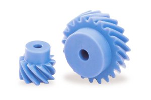
Can you explain the concept of screw gear threads and their functions?
Screw gear threads play a crucial role in the operation and functionality of screw gears, also known as worm gears. The threads are an essential component of the worm, which is the cylindrical gear with a helical thread wrapped around it. Here is a detailed explanation of the concept of screw gear threads and their functions:
- Thread Design: The threads on a screw gear, specifically the helical thread on the worm, are designed in a helical shape, resembling the threads of a screw. The helical thread is wrapped around the cylindrical body of the worm, creating a continuous spiral path along its length. The pitch of the thread refers to the distance between successive thread crests or valleys.
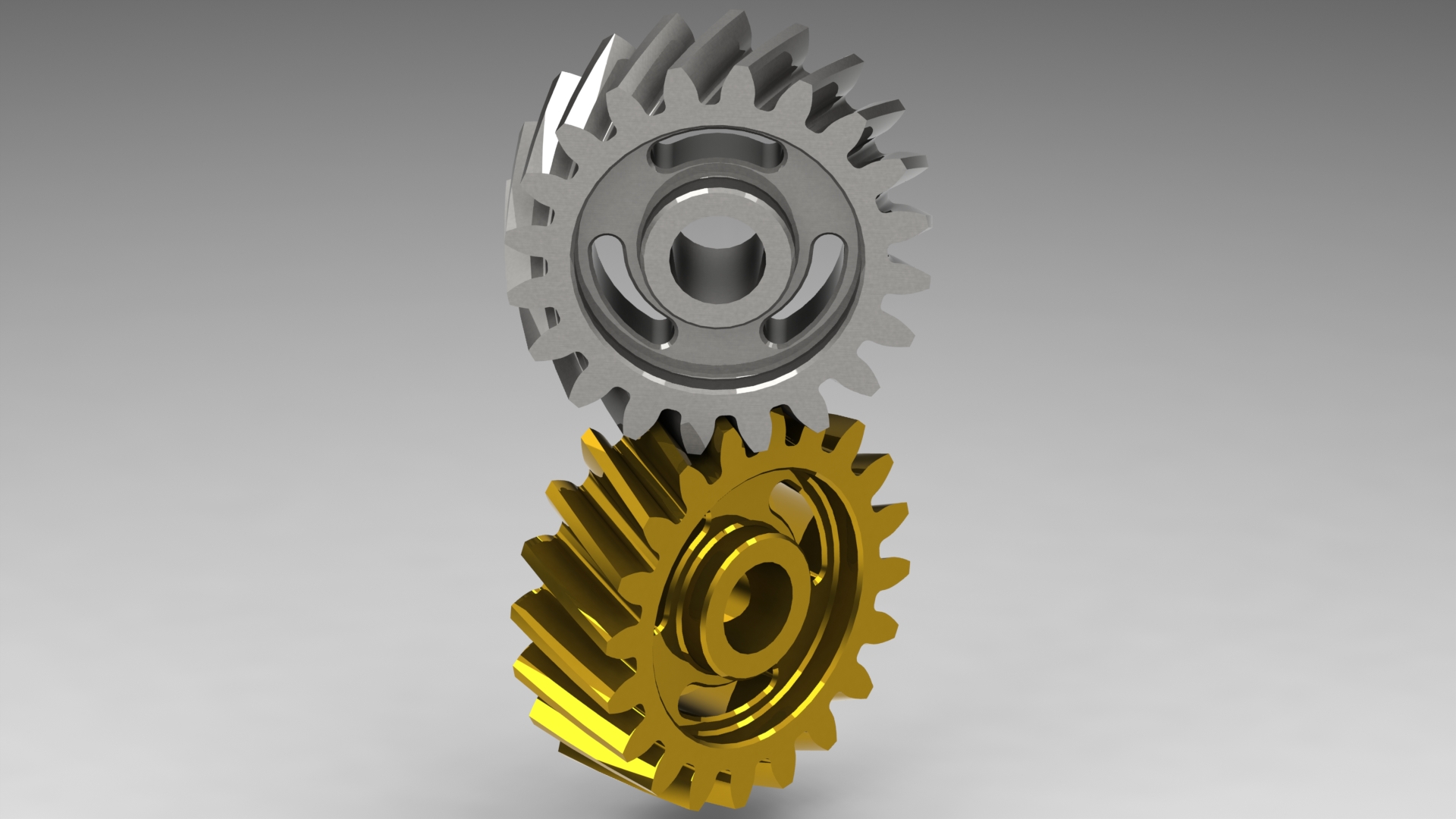
- Meshing with Worm Wheel: The primary function of the screw gear threads is to mesh with the teeth of the worm wheel. The helical thread of the worm engages with the teeth of the worm wheel, creating a sliding contact between them. As the worm rotates, the helical thread drives the rotation of the worm wheel, transmitting rotational motion and power.
- Gear Reduction and Torque Multiplication: The helical design of the screw gear threads allows for a large number of teeth on the worm wheel to be engaged at any given time. This results in a high gear reduction ratio, meaning that for each revolution of the worm, the worm wheel rotates by a smaller fraction. The gear reduction ratio enables torque multiplication, making screw gears suitable for applications requiring high torque output.
- Precision Positioning: Screw gear threads are crucial for achieving precise positioning in applications where accuracy is essential. The fine pitch of the helical thread allows for small incremental movements, enabling precise control over the rotation of the worm wheel. This feature is particularly advantageous in applications such as robotics, where accurate positioning and motion control are necessary.
- Self-Locking Action: The helical thread design of screw gears gives them a self-locking capability. When the worm is not rotating, the friction between the helical thread and the teeth of the worm wheel tends to hold the gear system in place. This self-locking action prevents the worm wheel from backdriving the worm, providing inherent braking or locking functionality. It ensures that the gear mechanism maintains its position without the need for additional braking or locking mechanisms.
- Efficiency and Lubrication: The sliding action between the screw gear threads and the teeth of the worm wheel introduces more friction compared to other types of gears with rolling motion. This sliding motion affects the efficiency of the gear mechanism, resulting in higher energy losses and heat generation. Proper lubrication with appropriate lubricants is essential to minimize wear, reduce friction, and improve the overall efficiency of the screw gears.
Overall, screw gear threads enable the meshing and transmission of rotational motion and power between the worm and the worm wheel. They facilitate gear reduction, torque multiplication, precise positioning, and self-locking action. Understanding the design and functions of screw gear threads is crucial for utilizing screw gears effectively in various applications.


editor by CX 2023-09-07